Research projects of Metal Cutting
Regarding deep-hole drilling with high standards of machining quality, the demands on a high accuracy and surface quality are increasingly accompanied by requirements concerning the hole rim zone. These include, for example, the meeting of a defined residual stress condition or the guaranteeing of given structure characteristics. In order to reliably achieve the desired results, autofrettage or burnishing and rolling processes are carried out after the drilling process. It would be desirable to adjust defined hole characteristics already during the drilling process so that no subsequent machining operations are necessary any more in the ideal case.
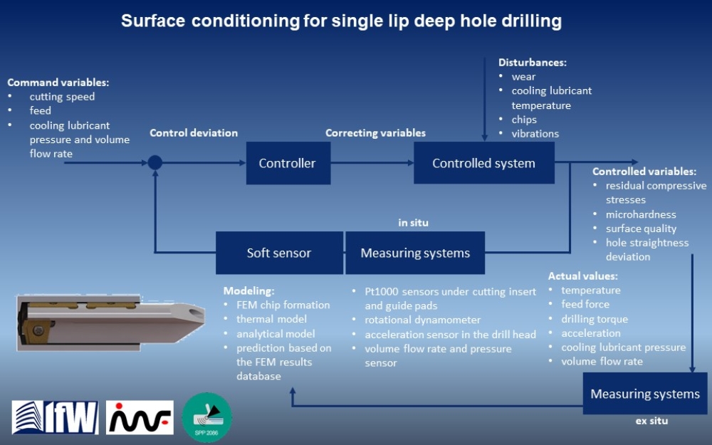
Hence, the goal of this research project, carried out within the Priority Programme SPP 2086 „Surface conditioning in machining processes“ by the German Research Foundation (DFG), is to measure the parameters influencing the course of the drilling process. The purpose of that is to be able to specifically change the process conditions with a controller and thus to exert a defined influence on the characteristics of the hole rim zone (e.g. residual stress, hardness and roughness).
A subgoal of this research project is concerned with developing and providing a sensor-integrated tool with which it is possible to establish in process the thermomechanical condition in the chip forming area as well as the arising tool vibrations. Within the framework of these developments, a combined numerical-analytical model will be created which makes it possible to conclude the actual temperature in the chip forming area from the sensor data.
A further subgoal is concerned with developing a cutting model and a material model with which it is possible to reproduce the correlation between the thermomechanical load condition in the chip forming area and the characteristics of the hole rim zone as well as to predict it so that it is not critical in terms of time. The output variables of the model are to provide information about the thermomechanical condition that has to be kept up in the chip forming area in order to achieve the desired rim zone characteristics. A further analytical model with in-process capability has to be created here as well, serving as a basis for the actual process controller. This model is to compare the output variables of the cutting and material model with the data measured by the sensory tool and is to derive suitable manipulated variables from the evaluation of the deviations.
This model can serve as a basis for the controller, which communicates with the control of the machining centre via a suitable interface and provides specifications about cutting data such as cutting speed or feed in order to be able to specifically adjust the surface characteristics of the drill hole.
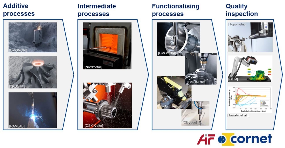
The Ad-Proc-Add project deals with the investigation into additive-subtractive manufacturing (ASM) chains. The goal here is to understand in detail how material and component properties of additively manufactured and remachined workpieces depend on and interact with process parameters, production strategies and boundary conditions. The vision behind it is to be able to adjust the workpiece properties with regard to geometry, surface and base throughout ASM process chains so that predefined requirements can be met. In this way it will become possible to specifically design and implement additive-subtractive manufacturing chains for various industrial applications. For that purpose, an international network of research associations and institutes has been built up to concentrate the necessary expertise in the fields of additive manufacturing, material removal processes, process monitoring and control, machines and facilities, simulation and optimization as well as energy efficiency analyses.
In this networked research approach, the synergy and capacity of the partners involved can be used in an optimal way. Thus, it will be possible to realize extensive experimental investigations into the correlations between parameter adjustments and influences onto the workpiece properties in additive and subtractive process steps. Furthermore, this will enable correlation analyses, detailed examinations of physical effects as well as methods for process monitoring and quality testing.
The findings of this projects will be used to derive novel tool concepts, strategies for the 3D printing of metal parts, methods for a high-quality design of remachining processes, system prototypes for instruments and devices as well as new industrial services. Moreover, the knowledge generated will enable component manufacturers as well as system and service providers to develop new products with extended functionality. In addition, it will enable end users to realize ASM process chains with a greater productivity and economic as well as ecological efficiency.
The project will result in a digital compendium that is based on a new performance measuring system and can be used by design and production engineers as well as service personnel. The project is accompanied by a user committee from all relevant market segments: tool, 3D printer and machine tool manufacturers, software and service providers as well as end users. The intensive communication with the industry partners will guarantee that the results to be worked out are relevant to and usable for industry.
This project dealt with the potential for substituting ceramic cutting tool materials for cemented carbide ones in the production of sawing tools.
The goal of the project was to optimize the production of ceramic cutting tool materials using the example of sawing tools, in order to be able to provide economical alternatives to cemented carbide cutting tool materials for the mass market. The scientific objective was to understand the efficiency of the cutting edge in interrupted cutting and to design joining and grinding processes of ceramic saw teeth. The findings gained were applied to concrete cases (milling tools, circular and band sawing tools).
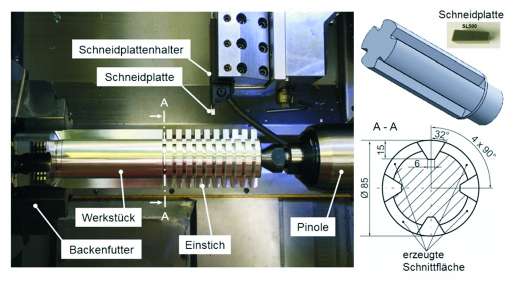
The essential results of the project were that the achievable tool life in the most important machining processes with interrupted cutting (e.g. sawing) depends on the changing mechanical and thermal loads as well as on the geometry and the wear behaviour of the tool. For that reason, a model process based on the classic recessing operation was elaborated, with which it was possible to model the conditions of circular sawing and compare cutting tool materials. The workpiece bodies were designed so that the loading of a tooth in the sawing process could be modelled. Figure 1 shows the set-up of the model test in the lathe (Gildemeister CTX 420 linear) used as well as an exemplary workpiece specimen made of S355JR structural steel.
In the project, experiments were not only carried out with S355 structural steel but also with GG25 and GGG60 grey cast iron and EN-AW-7075 aluminium. Ceramic recessing inserts made of oxide (SN 60), non-oxide (Beta-Si3N4) and mixed ceramics (Alpha/Beta-SiAlON) were used for the qualification in interrupted cutting. Recessing inserts of MG 12 cemented carbide with the same recessing width were examined as reference tools.
It could be proved that the developed model test is suitable for a quick and cost-effective qualification of ceramic cutting tool materials as well as an optimization (design) of the cutting edge geometry in interrupted cutting. The results gained showed that the non-oxide and mixed ceramics have a great potential for the machining of GG25 cast iron in interrupted cutting. Hence, these two ceramic cutting tool materials could be used for substituting cemented carbide in this concrete application.
The project was carried out in cooperation with Fraunhofer IPA and the KFS of Furtwangen University as well as several industrial enterprises.
Funded by: Baden-Württemberg Ministry of Finance

Development of an adaptive control (Adapt-i-Cut) – Subproject: „Development of the theoretical basis for predicting the resultant forces to optimize a CAM path planning“
For the process planner, it is extremely informative to know the resultant forces and the load curves, for example, in order to detect critical areas along the tool path. New analytical cutting models make it possible to quickly calculate the resultant forces along a complete NC tool path.
Modern CAM systems are capable of creating not only a classic, predefined path layout but also a tool path on the basis of geometrical engagement conditions that are as constant as possible. Despite of this approach, it is not always possible to avoid substantial alterations in the kinetic cutting characteristics of individual path segments as well as idle travel. There may be peak resultant forces of up to 70% in relation to the nominal values. This leads to an increased tool wear and risk of tool breakage, a reduced accuracy and quality of the machined component as well as to unstable processes in unfavourable circumstances.
A possible improvement may be to change from geometrically to kinetically constant engagement conditions between tool and workpiece. However, a guarantee of kinetically constant engagement conditions requires to determine the resultant force for each path point in advance.
For that purpose, a novel, completely analytical cutting model for milling processes was developed and implemented in this project. The crucial advantage here is an essentially more general modelling, allowing a valid prediction of resultant forces at any time even in the case of greatly varying engagement conditions and dynamically variable technology parameters – without time-consuming series of tests.
In a further integration step, this makes it possible to additionally compensate the deflection and compliance in the form of a location-adapted derivative path action already during the NC programming in the CAM system. In this way, it is possible to considerably improve the net shape and accuracy, especially when using long, slim tools.
Funded by: Central Innovation Programme for small and medium-sized enterprises - ZIM/AiF
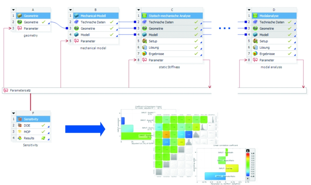
In this research project, the dynamic and static characteristics of circular sawing tools were examined and simulation models were made to reproduce these characteristics. The investigations were focused here on the influence of the laser ornaments made into circular saw blades and their fillings as well as on the flange joint It was analysed here how the decisive parameters, such as the surface quality in the joints and the contact pressure, influence the characteristics of the system. In model tests, the individual effects were examined in an isolated way. Then the complexity of the tests and simulations were being gradually increased in the course of the research project, in order to be able to model the interactions of the influencing factors. The collected results were applied to the entire rotating model including clamping and then validated by experiment, in order to finally carry out a sensitivity analysis of the influencing parameters. The results gained in the analysis showed that neither the microslip in the flange interface nor the characteristics of the filling had a considerable influence on the system behaviour in the unloaded system. By means of the shape and the arrangement of the slots as well as the prestress applied by the flange, it was, however, possible to clearly influence the system’s static and dynamic characteristics.
The project was carried out in cooperation with the Institute for Nonlinear Mechanics (inm) at the University of Stuttgart.
Funded by: DFG
The goal of this research project was to better understand the abrasive process in the ultrasonically assisted machining of stone. Influencing factors and working mechanisms that are relevant to the process were investigated here as they have not been sufficiently described yet. It was possible to gain fundamental insights into the process flow by means of linear scratch tests with a single diamond grain fastened to an ultrasonic transducer. The contact process between the diamond grain vibrating at high frequency and the stone specimen moved perpendicular to it in a linear motion was visualized by means of a high-speed camera. The evaluation of the video recordings and the force progressions showed that microhammering and a three-phase contact process (impact contact, penetration and separation) arose in ultrasonic processes. In addition, it could be proved that there was a correlation between the dominating chip forming mechanism and the cutting speed in vibration superposition. At low cutting speeds, chips were formed due to the fact that the diamond flank face hit the specimen surface (microhammering and secondary chip formation). In contrast to that, chips were mainly formed in front of the cutting edge (primary chip formation) at high cutting speeds. Moreover, two mechanisms that were acting in exactly the opposite way and influencing the process force were detected in ultrasonically assisted scratch tests. On the one hand, an increase in the vibration amplitude in the contact zone led to a decrease in the resultant force due to the growing velocity of vibration and the resulting reduction in friction. On the other hand, a higher vibration amplitude affected the effective depth of cut so that the chip cross-sectional area and the resultant force increased.
The above-mentioned process was described with models verified by experiment. For that purpose, the process and the system were divided into the following subsystems: tool, material removal, process forces, kinematics and ultrasound system. Afterwards, these subsystems were modelled separately and then put together to an iterative total model. The calculated process load was imposed on the ultrasound system, and the resulting vibration behaviour of the system was established. Each iteration step was carried out with the recalculated kinematic boundary conditions. To couple the submodels, a generic framework was developed with which all sorts of and any number of submodels could be connected. The created total model presented a useable tool for designing the system components.
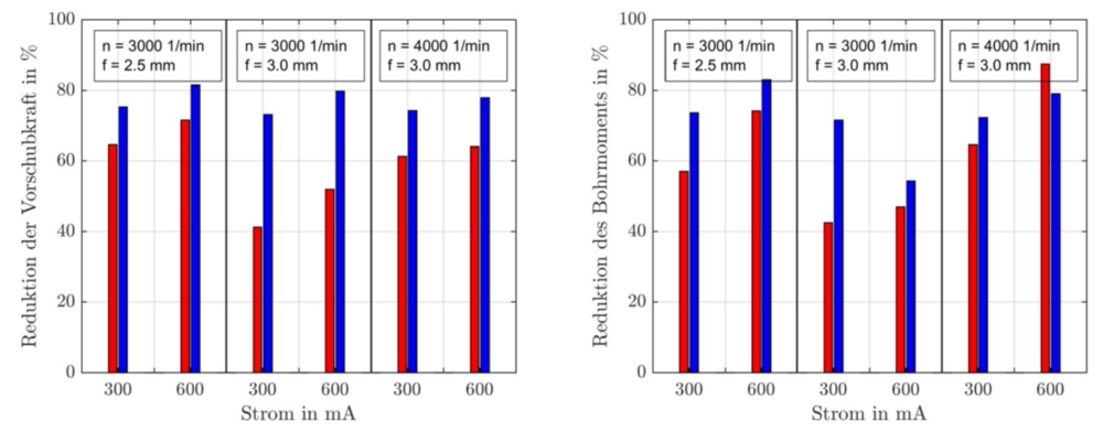
By means of model-based parameter studies, the bearing of the ultrasonic transducer was found to be essential for the vibration behaviour under load. A correspondingly optimized transducer-tool combination was established with the total model as well as an optimization algorithm and then built. Drilling and milling tests were carried out with both vibration structures. The optimized system showed a greater reduction in process forces (68-90 %) than the initial system (41-80 %). In addition, the optimized vibration structure proved to be more robust towards changes of the process parameters. The optimized system also showed an improved behaviour with regard to electric power.
Funded by: DFG
Contact

Rocco Eisseler
Dr.-Ing. Dipl.-Gwl.Team Leader Metal Cutting